d05
Newbie

Joined: August 2018
Posts: 6
Location:
|
Post by d05 on Aug 17, 2018 10:15:53 GMT
For the love of Zues someone please clear this up for me... I'm trying to follow the information on one of the thread pages after doing much research, Model 2 VA9 board. Does the example in the picture make sense and is that how to do it if you don't want to lift up pin 79 on the chip? I've removed the bridge from JP2 and used JP1 as my 5V and JP2 as ground. I've seen that you cut the trace at TR103 and use wire to connect it to the middle connector of your switch. How does that sound and will this work? Thanks for you help it's just that I'm reading a lot of different things and going down a rabbit hole quickly. -=D 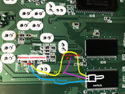 |
|
|
|
Post by zyrobs on Aug 17, 2018 14:47:16 GMT
That picture will work, but you'll have to solder to the thin pcb trace and route it over to the other side of the board. That could easily be torn off. I'd cut the trace leading to the via as marked on the pic, then on the upper side of the pcb, solder 28AWG wire inside the via (it's thin enough to get inside the via), connect it to 5V through a 20k resistor. Then wire up a switch between a ground point and the side of the resistor that connects to the 28awg wire. There's an empty capacitor slot right there that can provide +5v and GND connections. Something like this: 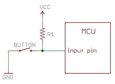 I think that's how I used to do it, last time I modded a unit like that. Maybe with 1/8W resistors you could solder directly into the via but I have not tested that. Alternatively you can forego the resistor and just connect 28AWG wire to the via as the middle point of your switch, and +5V and GND on the sides. But it is safer to use to use a pullup resistor. |
|
|
|
Post by blackfrancolin on Nov 6, 2018 3:24:40 GMT
In response to your PM, The picture you've shown in your post is the exact same picture that was on the site that was linked in my post (which is now obviously down). Just follow it. Be brave and cut that trace with a stanley knife. Best way to do it, is to place some electrical tape (or any thick tape) on either side of and all around the area you are about to cut, so that you don't accidentally slip and cut something else! Don't go too deep. I didn't get 5V or Ground from the same place as that picture though. I got it from the part of the board where the power supply pins are (underside). Google an image of it. Or just use what's in the picture.Use very thin solder (0.25mm). zyrobs suggestion is great too...if you can understand it! I didn't use a resistor. Hope this helps. Or I may be talking to myself since this thread is now months old.
|
|
klesh
Lurker
Joined: July 2022
Posts: 1
Location:
|
Post by klesh on Jul 6, 2022 12:34:56 GMT
Hello For the switc 60/50Hz saturn va9 I cut the connection (bridge) on jp2 and I got a black screen xD. So i re make the bridge and i did this and it's work. Thank's for the sharing of information anyway    |
|


