|
|
Post by endrien on Aug 10, 2009 15:13:35 GMT
So my board is the same as the first on this page www.mmmonkey.co.uk/console/sega/saturnregion3.htmBut I'm not really sure how I would solder the wires(Not how to solder, just where) and how I would wire it to a switch. Any help is appreciated, thanks! |
|
|
|
Post by endrien on Aug 10, 2009 16:02:31 GMT
I know how to wire up the normal points, but how do I do the common points? On mmmonkey it shows 1 common wire for 6/7 and 2 for 10/11. Would I put the 6/7 on one part of the DPDT switch and both the 10/11 on the other part?
|
|
mick_aka
 Kickin' it lively!
"Mick is moderately adequate."
Kickin' it lively!
"Mick is moderately adequate."
Joined: April 2007
Posts: 9,817
Location:
XBL: mickloaf
PSN: mickloaf
Nintendo ID: segamick
|
Post by mick_aka on Aug 10, 2009 17:39:15 GMT
Drop him an email at: web@mmmonkey.co.uk to clarify, he's a nice chap  |
|
|
|
Post by endrien on Aug 10, 2009 18:16:15 GMT
Thanks , I'd really like to get this working soon before I get my nights jap version and a few other games. I also want to get vampire savior with the ram cart....I've got awhile before that ends on ebay though. |
|
|
|
Post by termis on Aug 11, 2009 1:27:32 GMT
The pics show 3 common points, one each for jumpers 6/7, 10/11, and 12/13. (Those are not two common points for 10/11) From what I'm reading, it seems that you're doing a 2-country (US-JP) switch mod, is that correct? If that's the case, you need solder one end of a wire to a common point 6/7 and 10/11, and disregard 12/13. (in other words, ignore where mmmonkey is soldering the pink wire -- he's doing the 3-country mod) Read section 9.6 of this guide and that'll tell you exactly where you need to put the wires (a total of 6 for the 2 country-mod). www.gamefaqs.com/console/saturn/file/916393/6458If you're doing a 3-country mod, then you need to use all three common points (plus 2 more, one for ground, and other for +5v) and connect those to a custom built circuit board as mmmoney has shown in his guide: www.mmmonkey.co.uk/console/sega/saturnregion.htm |
|
|
|
Post by endrien on Aug 11, 2009 1:43:27 GMT
I'm following this tutorial(Might need to watch part 3 to understand what exactly hes showing): www.youtube.com/watch?v=AVgbHH-nAIM&feature=response_watchand yes I'm doing a 2 region mod. I have a DPDT switch. I'm a little confused as the guy on youtubes jumpers are all together, unlike mine where there in different places. |
|
|
|
Post by endrien on Aug 11, 2009 1:48:30 GMT
Would this be mine? Also why is his DPDT switch like Left Right A D B E C F Mine looks like 1 2 3 4 5 6 It looks like mine except mine isnt 11 10 its 11 10( www.mmmonkey.co.uk/console/images/sega/satregion3.jpg) Version 2
JP# LeftRight
JP11 X A
JP10 B C
JP# LeftRight JP# Left Right
JP6 D X JP7 F E
In this version the power cord is notched. This version was
manufactured from approximately 8/95 - 3/96. You will have to remove
two small components from either JP7 and JP10 or JP6 and JP11. They
are unimportant and serve merely to short the jumpers that establish
the world area in which your machine is designed to operate.
JP10 & JP11 are located on the top of the main motherboard near the
center in the configuration shown above. JP6 & JP7 are on the bottom
in a side by side configuration like in the table above. The common
post of JP6 & JP7 is on the right, while the common post of JP10 &
JP11 is on the left.
-------------------- |
|
|
|
Post by termis on Aug 11, 2009 2:06:14 GMT
just turn your switch around vertically and follow the soldering points. That if you labeled yours as:
1 2 3
4 5 6
turn that vertically so that it becomes (doesn't matter which way),
4 1
5 2
6 3
then relabel the points so that it becomes
A D
B E
C F
And from your description (and the pics), your motherboard seems more like a version 4 on the gamefaqs guide, not version 2. Double check that.
|
|
|
|
Post by endrien on Aug 11, 2009 4:45:09 GMT
|
|
|
|
Post by termis on Aug 11, 2009 5:40:07 GMT
Try this out -- it should do it. Disclaimer: You're on your own if you blow something, though I've never, ever, messed up a saturn this way. If you want to see inner the details of what's going on, a more thorough explanation can be read ->here<--. 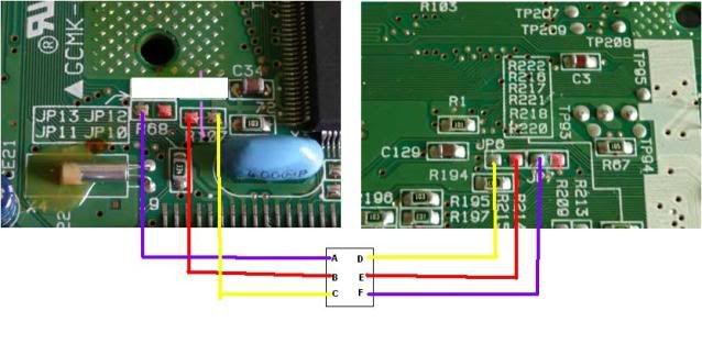 Also, you shouldn't have touched the bit I cut out (the white box) -- that is, the jumpers/trace that was on JP13 should've been left on there and NOT removed/cut (if you did, connect the two points back again). A BIG assumption I have at this stage is that your system is an NTSC system (US/Japan). If it's a EU system, stop here and let me know, as you have to do something else. Also, you should've removed all the jumpers/cut the traces that are between Jumpers 10/11 or 6/7. Try soldering the above points and see how it works out. |
|
|
|
Post by endrien on Aug 11, 2009 5:49:12 GMT
I'm tired atm, gunna go to bed. Thanks ALOT for that diagram! It is a US version. I haven't touched anything jumper wise yet, I need to get a smaller soldering iron tip which I'll do tomorrow.
|
|
|
|
Post by endrien on Aug 11, 2009 16:52:59 GMT
On both settings(On/off) it says game disk unsuitable for system(US disk, I don't have a jap game to test till I get it in the mail) BUT it will still play the games music?
|
|
|
|
Post by endrien on Aug 11, 2009 17:40:24 GMT
Sorry for the triple post....Anyways. I'm either extremely fucked or extremely lucky, I'm not sure which yet. Soldering went bad when I tried to do a different configuration and ripped off 2 jumpers(the solder came all off and a bit of the trace came up). So I removed all wires I soldered and put it back together, it turns on and trys to read the disk but it says "game disk unsuitable for this system" for a US disk. I'll have to wait and see what a JP disk says. If I'm extremely lucky it will read a jp disk.....
It will still play the disks music btw.
Edit: I think only one trace that came up matters, shouldnt I be able to follow that to a chip somewhere and solder that to my DPDT?
|
|
|
|
Post by termis on Aug 11, 2009 23:22:55 GMT
Go into the systems setting, and take a look at the bottom right hand corner of the screen. You should see a string of text that says something like..
NTSC-x-V1.00
What does it say? the "x" should be a single hex digit. Ideally, you're trying to get it to say 1 (Japan) or 4 (US), depending on switch position.
Let me know what digits it displays so far and that should give me an idea where it went wrong. Also if you can get close up pic of the soldering spots that would be great.
|
|
|
|
Post by endrien on Aug 11, 2009 23:32:55 GMT
Wtf? It says NTSC-C-V1.00a
I'll get a close up pic in a few minutes..Do you have msn or something?
|
|