|
|
Post by blackfrancolin on Feb 16, 2016 17:56:42 GMT
I want to modify Model 2 Saturn so I can select between 50/60Hz video frequency. From what I can tell, I can achieve this in a number of ways. I have found lots of guides and even a few videos instructing to lift pin 79 VDP. This looks very delicate and I have read on here and other places that it's risky and that there are safer ![]() ways of doing it. However the information I can find is confusing/not as clear as I'd like since there's so many different motherboard revisions. I am not brilliant at electronic jiggery pokery but I'm quite confident that I can cut traces and solder wires to it. I just don't know where to do it. Can anyone point me to some guides or images? I have posted a picture of my Saturn serial number if that helps. I know this has probably been covered on here many times and I apologise for making a post on the topic, but searching through the posts has yielded no results. Unless I sit here for hours doing it. I have found the following guide: djoen.dommel.be/Console/saturn/saturn-model2.html But again, I am uncertain if this is correct for my machine. Thanks for your time  |
|
|
|
Post by zyrobs on Feb 16, 2016 20:18:33 GMT
That's a VA9 machine, same type as in the link you posted.
On those models I normally cut the common point between JP1/2, as well as the line that connects the common point to the PLL (IC20) pin 1. Then I solder the cable to the now-isolated JP1 common point (since you cut two traces it now only leads to the VDP2 pin 79), and I connect a ground pin to the PLL pin 1 just to make sure it stays grounded. On VA13 PAL units the PLL is different so you can ignore anything related to that (less traces to cut on those machines).
|
|
|
|
Post by blackfrancolin on Feb 17, 2016 5:30:26 GMT
So I just basically need to follow the guide that I linked to? I have been searching the posts on this board and I found another thread where your good self has answered somebody else with a similar question. segasaturngroup.proboards.com/thread/6888 . You've explained/shown where to cut the point to the PLL pin 1. But the images on there are not loading. Any chance you could show those images again (assuming you still have them)? Thank you. |
|
|
|
Post by blackfrancolin on Feb 17, 2016 5:36:59 GMT
Forgot to add, are there any particular switches anyone could recommend? I want to be able to locate it in the battery compartment without having to cut the battery cover since it's going to be in 60hz most of the time anyway. Some folks have been placing it near and sort of underneath the VCD slot. Any size information would be helpful. I don't have any electronics stores nearby, so I would have to buy online, and I'd rather avoid having to buy loads of multiple size switches online. I was thinking something like this: www.ebay.co.uk/itm/20-PCS-Black-SPDT-ON-Off-Miniature-Slide-Switch-Electronic-Components-/351353359962 |
|
|
|
Post by zyrobs on Feb 17, 2016 5:51:36 GMT
The location to cut is somewhere under the middle white paint on the PCB. I don't remember exactly where, I re-trace it every time I do the mod. The guide you linked to also works, but scraping the protective paint off a thin trace so you can solder a cable to it, that's about as safe as lifting the pin in my opinion. For switches, I use these (I think? It's been a while I had to buy): www.tme.eu/en/details/s3p/slide-switches/You have the black plastic tray around the battery, and there's a small crevice on its side where you can fit in these switches, if you fold up their fins. Fold them too tight and the switch will be too loose. It's a bit finicky but you get it in there so it stays stable, especially so since the heat shield pushes down on it as well. MPEG carts fit above it, a bit tight, but it fits. It is probably safer to use a toggle or a rocker switch, but I do not like cutting up the cases. |
|
|
|
Post by blackfrancolin on Feb 29, 2016 7:12:12 GMT
Thanks a lot for all your help and time. I've just manged to get this done. I was waiting to finish up on a game before I attempted it just in case things went wrong. About two hours and 10 cigarettes later (I was meticulous about disassembly, labeling things as I went along - actually, it's the reassembly where I'm prone to mess ups) it's all looking good. Fairly straight forward. Cheers.
|
|
moonston3
Newbie

Joined: February 2016
Posts: 17 
Location:
|
Post by moonston3 on Feb 29, 2016 16:11:33 GMT
Hi all I'm wanting to do this mod on my model 1 or model 2 Saturn is this tutorial OK to follow just solder 2 wires onto the 2 ports near the battery cable or is this wrong. Do you need to still cut lines on motherboard thanks Here's link to vid m.youtube.com/watch?v=86hSRbpzDE0 |
|
|
|
Post by blackfrancolin on Mar 1, 2016 8:21:11 GMT
You need to know which Mainboards your Saturns have got. Either find out by looking at the serials (you can maybe post them here), or you can remove the tops from the console and see that way (VA + number). The method shown in that video apparently only works on a small number of consle types.
|
|
cobbperrin
Lurker
Joined: March 2016
Posts: 1
Location:
|
Post by cobbperrin on Mar 30, 2016 12:14:27 GMT
As per my knowledge on those models they normally cut the common point between JP1/2, as well as the line that connects the common point to the PLL (IC20) pin 1. Then I solder the cable to the now-isolated JP1 common point. On VA13 PAL units the PLL is different so you can ignore anything related to that. www.7pcb.com/HDI-PCB.php |
|
d05
Newbie
Joined: August 2018
Posts: 6
Location:
|
Post by d05 on Aug 16, 2018 17:08:08 GMT
Hi mate,
I have a model 2 VA9 board and am in the same boat as you, so much information but conflicting at the same time. Which method did you end up going? Did you use the switch on JP1 and 2 only? Or cut the trace next to it also?
Thanks
-=D
|
|
captainkael

Joined: March 2012
Posts: 2,485
Location:
XBL: CAPTAINKAEL
PSN: CappyK
|
Post by captainkael on Aug 16, 2018 19:50:07 GMT
Hi mate, I have a model 2 VA9 board and am in the same boat as you, so much information but conflicting at the same time. Which method did you end up going? Did you use the switch on JP1 and 2 only? Or cut the trace next to it also? Thanks -=D Seeing how old this thread is I recommend making a new one with a specific description of your problem. |
|
d05
Newbie
Joined: August 2018
Posts: 6
Location:
|
Post by d05 on Aug 17, 2018 10:12:35 GMT
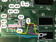 Hi, I'm trying to follow the information on this page after doing much research, Model 2 VA9 board. Does the example in the picture make sense and is that how to do it if you don't want to lift up pin 79 on the chip? I've removed the bridge from JP2 and used JP1 as my 5V and JP2 as ground. I've seen that you cut the trace at TR103 and use wire to connect it to the middle switch. How does that sound and will this work? Thanks for you help it's just that I'm reading a lot of different things and going down a rabbit hole quickly. -=D |
|
d05
Newbie
Joined: August 2018
Posts: 6
Location:
|
Post by d05 on Aug 17, 2018 10:13:11 GMT
Thanks man good suggestion will do!
|
|


